Our Store
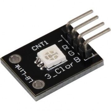
KY-009 RGB 3 Color Full Color LED Module
KEYES KY-009 RGB 3 Color Full Color LED SMD Module For Arduino AVR PIC
Product Parameters:
1. Using 5050 full color LED.
2. RGB tricolor current-limiting resistance to prevent burn out.
3. Through the PWM adjusting three primary colors can be mixed to obtain different colors.
4. With a variety of single-chip interface.
5. Working Voltage: 5V.
6. LED Drive Mode: Common cathode driver.
A LED-module which provides a red, blue and green LED. These are connected with a common cathode. A resistor is necessary for different voltages.
Vf [Red]= 1,8V
Vf [Green,Blue]= 2,8V
If= 20mA
Pre-resistor:
Rf (3,3V) [Green]= 100Ω
Rf (3,3V) [Red]= 180Ω
Rf (3,3V) [Blue]= 100Ω
[for example using of ARM CPU-Core based microcontroller like Raspberry-Pi]
Rf (5V) [Green] = 100Ω
Rf (5V) [Red] = 180Ω
Rf (5V) [Blue] = 100Ω
[for example using of Atmel Atmega based microcontroller like Arduino]
Code example Arduino
int Led_Red = 10;
int Led_Green = 11;
int Led_Blue = 12;
void setup ()
{
// Output pin initialization for the LEDs
pinMode (Led_Red, OUTPUT);
pinMode (Led_Green, OUTPUT);
pinMode (Led_Blue, OUTPUT);
}
void loop () //main program loop
{
digitalWrite (Led_Red, HIGH); // LED will be switched on
digitalWrite (Led_Green, LOW); // LED will be switched off
digitalWrite (Led_Blue, LOW); // LED will be switched off
delay (3000); // Waitmode for 3 seconds
digitalWrite (Led_Red, LOW); // LED will be switched off
digitalWrite (Led_Green, HIGH); // LED will be switched on
digitalWrite (Led_Blue, LOW); // LED will be switched off
delay (3000); // Waitmode for another 3 seconds in which the LED status will be shifted.
digitalWrite (Led_Red, LOW); // LED will be switched off
digitalWrite (Led_Green, LOW); // LED will be switched off
digitalWrite (Led_Blue, HIGH); // LED will be switched on
delay (3000); // Waitmode for another 3 seconds in which the LED status will be shifted.
Code example Raspberry Pi
# Needed modules will be imported and configured.
import RPi.GPIO as GPIO
import time
GPIO.setmode(GPIO.BCM)
# The output pins will be declared, which are connected with the LEDs.
LED_Red = 6
LED_Green = 5
LED_Blue = 4
GPIO.setup(LED_Red, GPIO.OUT, initial= GPIO.LOW)
GPIO.setup(LED_Green, GPIO.OUT, initial= GPIO.LOW)
GPIO.setup(LED_Blue, GPIO.OUT, initial= GPIO.LOW)
print "LED-Test [press ctrl+c to end]"
# main program loop
try:
while True:
print("LED Red is on for 3 seconds")
GPIO.output(LED_Red,GPIO.HIGH) #LED will be switched on
GPIO.output(LED_Green,GPIO.LOW) #LED will be switched off
GPIO.output(LED_Blue,GPIO.LOW) #LED will be switched off
time.sleep(3) # Waitmode for 3 seconds
print("LED Green is on for 3 seconds")
GPIO.output(LED_Red,GPIO.LOW) #LED will be switched off
GPIO.output(LED_Green,GPIO.HIGH) #LED will be switched on
GPIO.output(LED_Blue,GPIO.LOW) #LED will be switched off
time.sleep(3) #Waitmode for 3 seconds
print("LED Blue is on for 3 seconds")
GPIO.output(LED_Red,GPIO.LOW) #LED will be switched off
GPIO.output(LED_Green,GPIO.LOW) #LED will be switched off
GPIO.output(LED_Blue,GPIO.HIGH) #LED will be switched on
time.sleep(3) #Waitmode for 3 seconds
# Scavenging work after the end of the program
except KeyboardInterrupt:
GPIO.cleanup()


